Guide to Steam Systems Part 2 Steam Distribution
The steam distribution system is the important link between the steam source and the steam user.
An efficient steam distribution system must be capable of supplying good quality steam at the required rate and at the right pressure to suit the process requirements. It must do this with the minimum of heat loss and with minimum attention.
1.2 Steam Distribution
For an efficient distribution system some of the factors which must be considered are:-
- Steam Header
- The Pressure at which steam is Distributed
- The Size of the Steam Main
- The Steam Main layout and Drainage
- Air Venting
- Provision for Expansion
- Minimising Heat Losses
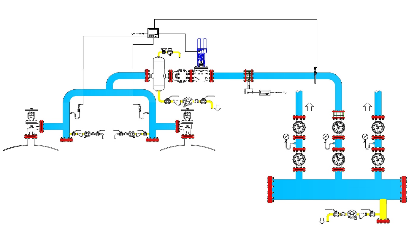
1.2.1 Steam Take-Off & Header Design
Steam flows in response to a fall in pressure. In a multi boiler installation, the ability of one boiler to supply steam as opposed to another is dependent upon pipework pressure.
Often there is little thought given to the interconnection between two or more boilers. It is assumed that providing the boilers are joined in some way then the distribution system will have access to their combined output. It is a flawed concept!
Boiler plant is installed to ensure that the factory's needs are met under all operating conditions. Providing that the main boiler has been sized to satisfy the maximum demand and that the distribution pipework is also sized on that capacity then there is no problem. All needs will be satisfied at all times, boiler priming and carryover will not cause undue problems.
However, when peak demand exceeds the boilers maximum output and factory needs have to be met by additional boiler plant then it is important to ensure that not only the distribution system, but also the interconnections between boilers are adequately sized and correctly installed.
Boiler manufacturers size crown valves and boiler safety valves on the maximum rated output at the designed working pressure. It is therefore normal practice to size the boiler off-take based on the crown valve flange dimensions. The fact is often overlooked that if the boiler is operated below its designed working pressure the off-take can be undersized. This, in itself, could adversely affect the boiler output. I.e. the lower the pressure the higher the volume flow rate of steam.
When two or more boilers are connected together the problems associated with undersized pipework increase.
The maximum generated steam output from boilers is stated as “From and At 100oC” (F&T) also referred to as „Maximum Continuous Rating' (MCR). The “from and at” rating gives the weight of water that the boiler is capable of converting into steam if the feed water was at 100OC and the steam was being generated at “Atmospheric Pressure”.
The actual maximum boiler output is therefore dependent upon the feedwater temperature and boiler pressure. Additional sensible heat is required to raise the water inside the boiler up to the temperature of the steam plus an amount equal to the difference between the actual feedwater temperature and 100OC.
A boiler rated at 9000kgs/hr with a designed working pressure of 10bar.g will have a maximum output of 8400kgs/hr with a feedwater temperature of 85OC. The crown valve will have been sized on maximum capacity at 10bar.g and would typically be 150mm. 150mm pipe work is suitable for this load but by operating the boiler at 6bar.g would require 200mm pipe work if pipe velocity is kept reasonable.
With one boiler, the result is the inability to supply the maximum weight of steam that the boiler is capable of generating. A drop in pressure across the distribution system will result. However, with two or more boilers interconnected, problems with boiler operation can also result. Instead of the load being shared equally amongst the boilers, one boiler will tend to supply the majority of the load and on occasion become overloaded whilst the remainder seldom delivers their true capacity.
If the lead boiler becomes overloaded and locks out then the load is immediately transferred to the next in line boiler. Which is unlikely to be on high fire and therefore unable to respond to the instantaneous increase in demand. It too can then lock out, transferring the load to the next, eventually resulting in all the boilers locking out. The correct design of boiler headers and interconnecting pipework will ensure that all connected boilers share the load evenly and are better able to satisfy varying production loads.
1.2.2 The Pressure at which Steam is Distributed
Steam of the best quality is produced by boilers working at or close to their maximum designed pressure. When the process requires a lower steam pressure this should be achieved by locally installed pressure reducing valves.
Distributing steam at the higher pressure means that the size of the mains can be kept to a minimum. Smaller steam mains have smaller heat losses with installation and lagging cost savings.
On an existing steam system, the overriding requirement is the minimum pressure required by the process, the size of the steam main and the distance that plant is from the boiler house.
When determining the distribution pressure we need to consider the following:-
- Maximum Safe Working Pressure of the Boiler
- Pressure required at point of use
- Pressure drop along the pipe due to frictional loss
- Heat losses across the pipe network.
1.2.3 The Steam Main Size, Layout and Drainage
Steam mains are required to supply the correct quantity of steam at the correct pressure and condition to the point of use. At the design stage, it is important to consider the system pressure drop when sizing the steam mains. Oversized pipework results in unnecessary expense in pipework, valves and lagging. Undersized risks steam starvation with greater risk of erosion, noise and water hammer resulting from high velocity flow rates.
Steam mains sized for maximum velocity flows of between 25m/s to 40m/s should be installed with a fall, of not less than 100mm in 10m, in the direction of flow to enable condensate to flow with the steam towards the drain pockets.
Line sized drain pockets are required at the bottom of rising mains and at between 30m & 50m of horizontal runs.
Condensate should be discharged as it forms at steam temperature and therefore the preferred trap is of the mechanical or thermodynamic type.
1.2.4 Air Venting
Air venting steam mains is of paramount importance and is far too often overlooked. Air is drawn into the system when the steam supply is shut off and the residual steam condenses. Small amounts of air are dissolved in the feed water entering the boiler and being non-condensable, accumulates in the steam space. Furthermore, incorrect water treatment can lead to carbon dioxide being released into the steam system. Provision must be made to automatically vent these gases from the steam system.
Automatic air vents installed above any possible condensate level at the ends of the steam mains and branches, will allow discharge of these non-condensable gases, promoting high heat transfer rates and reducing the possibility of corrosion.
1.2.5 Provision for Expansion
Pipes used to carry hot fluids, whether water, oil or steam, will expand in proportion to the temperature difference. The amount of expansion is easily calculated or read from suitable tables. The pipe expansion must be accommodated to prevent undue stresses from causing damage to the system. Accommodating the expansion can be achieved naturally, by virtue of having reasonable lengths and plenty of bends or by installing expansion loops or bellows.
An area which is often overlooked is the pipe connections between mains drainage points and adjacent condensate return lines. Some flexibility should be incorporated in the steam trap piping so that branch connections do not become overstressed.
1.2.6 Minimising Heat Losses
The specification of insulation materials is outside the scope of this report. It is clear, however, that if steam distribution is to be as efficient as possible then all appropriate steps should be taken to ensure heat losses are reduced to the economic minimum. In exposed locations, these losses can increase by 3 to 5 times. Proper insulation will reduce this heat loss to between 5% & 10%.
Adequate protection and waterproofing are essential especially in outdoor locations. The heat loss from a steam pipe to water saturated insulation can be as much as 50 times greater than from the same pipe to air.