Integrated Boiler House Control Part 2 - Handling boiler blowdown an alternative/personal view
Energy Efficiency
We are constantly encouraged to replace old equipment with new energy efficient units. Whether at home with fridges and washing machines or at work with the latest efficient electrical motors and compressors. All in the name of reducing our energy consumption.
Yet when it comes to steam boiler control, providing we, in the UK, conform to the HSE or CEA guidelines we appear to be content with wasting energy every time the boiler blows down or a weekly evaporative test is carried out.
Whilst the UK and the USA have slightly different approaches to ‘Boiler Blowdown’ neither of the systems employed recover any of the heat energy discharged to drain.
In the UK boiler blowdown vessel design evolved to emulate the blowdown pit’s functionality in as much as it must provide:
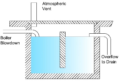
- A means of safely handling the flash steam generated as the temperature of the blowdown water drops from steam temperature to 100°C
- A water seal to prevent the flash steam discharging to drain.
- A means to cool the blowdown water so that the resulting water going to drain is at an acceptably low temperature.
With the introduction of the blowdown vessel to replace the blowdown pit it retained the water seal to precool the boiler water whilst safely controlling the depressurisation of the high temperature discharge.
The resultant flash steam vents to atmosphere whilst the remaining volume of hot water displaces its equal volume of the cooler standing water. A cooling water control system is installed to ensure that the discharge to drain never exceeds the local authority guidelines of 43°C.
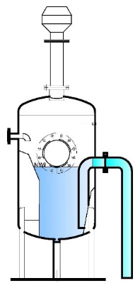
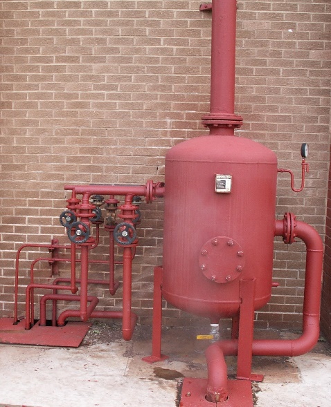
In the USA, they have a slightly different approach as the picture of a Lattner blowdown separator indicates. 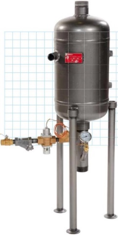
The blowdown separator is designed to separate the flash steam from the blowdown water and vent it to atmosphere.
The remaining hot water is cooled by thermostatically controlled cooling water control system.
The only relative difference is that with the USA system there is no requirement for the volume of standing water inside the vessel so the blowdown separator is much smaller.
On the downside, it requires a higher volume of cooling water which goes to waste and all the energy contained in the blowdown water is lost.
Apparently the UK system is better because it uses less cooling water. However, the initial cost for the vessel is higher and the installation is more expensive especially on multi-boiler sites where provision must be made to install the blowdown pipework beneath the boiler house floor in ducts or install a suspended floor to eliminate trip hazards. To assist cooling the blowdown vessel is frequently installed outside.
One drawback of the blowdown vessel that is not normally mentioned is the propensity of the bottom half of the blowdown vessel to corrode since it is constantly half filled with cold, oxygenated, water.
The fact that the blowdown vessel relies on the water seal to aide cooling is also one of its major drawbacks. When bottom blowdown valves are left open for extended periods the vessel pressure increases above the 3.5psi limit resulting in the loss of the standing water resulting in the high temperature boiler water cascading out of the vent and through the overflow discharging to drain.
To reduce the amount of energy lost to drain there are additional heat recovery systems available capable of recovering up to 90% of the heat normally lost from boiler surface blowdown. However, no attempt is made to recover the lost energy from bottom blowdown or the weekly boiler water evaporative test. The excuse being the possible build-up of solids inside any heat exchanger installed to recover the heat content from the bottom blowdown water.
An Alternative Solution
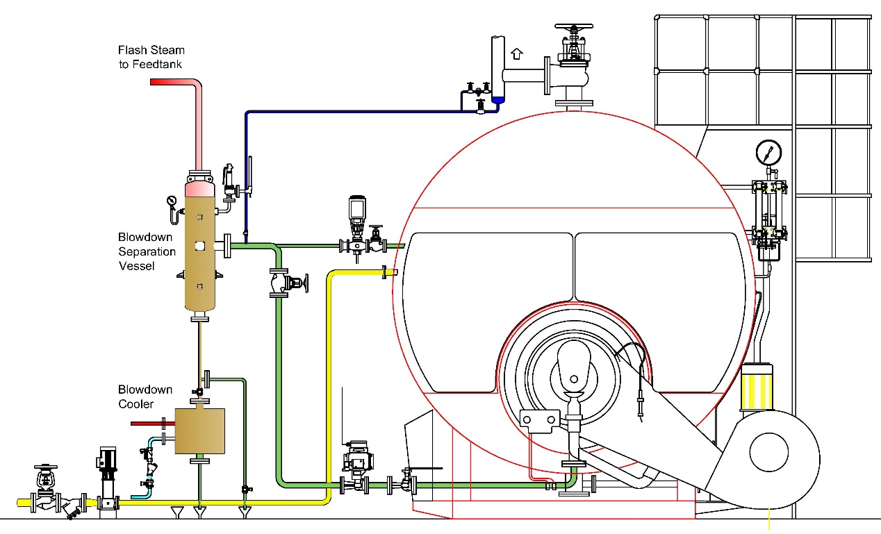
Controls 4 Steam believe that there is an opportunity for a hybrid blowdown system which uses less water than the USA system, eliminates the standing water in the UK system whilst remaining cost effective. One which enables all flash steam to be recovered to supplement feed tank heating whilst recovering 90% of the heat in all the blowdown water without recourse to a separate heat recovery system.
One that utilises a boiler mounted Blowdown separator into which, the bottom blowdown discharge pipe, surface blowdown line and the sight glass drains would be connected. Excess heat would be flashed off and piped to the feed tank whilst the blowdown water would then pass through a purposely designed cross flow heat exchanger where the heat from the blowdown water would be recovered by softened cold water make-up which in turn would discharge directly into the feed tank.
On multi-boiler installations each boiler would have its own dedicated Blowdown separator with one common cross flow heat exchanger to cool the water prior to discharge to drain.