Integrated Boiler House Control Part 1 “Boiler Feedtank” or “Hotwell” Design
To borrow a phrase from Xylem Corp., ‘Let’s Solve Water’ in this case the supply, storage, heating and delivery to the boiler of the feedwater.
Steam production is part of a dynamic system where freshwater is chemically treated stored in a feedtank heated and pumped into a boiler where the combustion process converts the energy contained in the fuel into heat energy, which is then transferred into the water and steam generated. Within this steam cycle there is a natural time delay between the distribution of steam from the boiler house and the return of condensate, during which time the boiler requires additional water. To ensure a constant supply of water is available a storage tank is provided.
 Boiler feed water tanks or “Hotwells” have, in the past, been treated simply as a water store with little attention paid to their true role in efficient and cost effective steam production.
Utilising an atmospheric feed water tank with additional water treatment is the normal extent of treatment with industrial boiler plant in the UK. The conventional feedtank design is broadly based on one hour water storage whilst maximising the volume of stored water.
When boiler houses were brick built and feedtanks installed on reinforced concrete mezzanine floors it was logical to maximise the water storage based on a cuboidal design so the rectangular feedtank became the norm. As the boiler house (Energy Centre) design changed to predominately, “A-framed” prefabricated construction does the same rule apply? Controls 4 Steam think not.
In modern Energy Centres there are no mezzanine floors so to ensure that there is always sufficient static head pressure (NPSH) to prevent boiler feed pump cavitation atmospheric feedtanks have to be elevated high enough to ensure that the normal water level (NWL) provides sufficient static pressure under all operating conditions. The rule of thumb is between 4 and 5 metres above the pump inlet. For the sake of argument let us say that we are catering for a 10,000kgs/hr 10 Bar boiler plant.
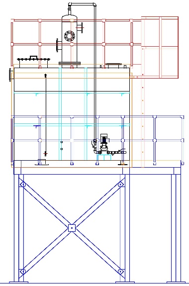
Typically the feed tank would be sized at 2m x 2.5m x 2m high but the NWL would only be about 1.5m from the base so the feedtank platform would need to be approximately 2.5m high which in turn means that a walkway and access ladder is required in order to access the tank and an additional ladder and handrail to gain access to the top of the tank. All of which adds considerably to the cost of installation and maintenance in providing the feedtank. There are also limits on the positioning of the feedtank: when you add a man’s height the total headroom from floor level is in the order of 6.5m.
Now the cost of the tank and its inherent drawbacks
With corrosion in mind feedtanks are predominately of stainless steel construction but there is a downside; stainless steel is expensive so to keep costs within reality 5mm or 6mm thick plate is used to construct the tank. To prevent it changing shape when filled with water the sides and base have to be strengthened, usually with Mild Steel channel, adding to labour and material costs. But stainless steel also work hardens, is more susceptible to stress cracking than carbon steel and it is not unheard of for tanks to leak due to stress cracking usually on the plates that have the steam injection connections on.
As previously stated the tanks are usually sized on 1 hours steam generation on multi-boiler installations or on the size of the boiler for standalone systems. But here’s the rub. As an atmospheric tank it has to have a vent to atmosphere and an overflow to drain. The vent has to be sized to prevent the pressurisation of the tank so, do you size the vent on the amount of steam released from the hot returning condensate, passing steam traps or the control valve’s maximum steam flowrate when self-acting temperature controls are fitted? Uncontrolled steam injection would boil the tank dry.
A good indication that the vent is undersized is when steam emits from the tank overflow after the build-up of pressure blows the water seal: helping to prevent damage to the tank but filling the Energy Centre with steam. Anyone for a sauna?
The need for an overflow reduces the useful storage by about 150mm (6”) add to that the ullage space, say 100mm (4”) for the intermittent condensate returns and an additional allowance for the difference between a cold fill and running conditions another 100mm (4”). Oh, and not forgetting that when you inject steam you also raise the water level by an equivalent amount. On a 10m3 tank the steam injection system will be sized on raising the tank contents from cold to operational temperature within 1 hour which equates to a steam load of about 1250kgs/hr adding 12.5% or 250mm (10”) to the tank volume.
Setting the level controls can have a marked effect on the amount of water lost to drain. Conductivity probes need to be cut to different lengths to suit the on/off switching levels trusting these are correct. With capacitance probes you can at least adjust the settings to get the best balance after commissioning. Whichever system is installed you had better make a total allowance of 600mm (24”) reducing the tank capacity from 10m3 to an operational holding volume of 7m3 or stand the cost of a larger tank.
Corrosion?
It is easy to justify materials of construction based on the emotive word ‘corrosion’ and the effect oxygenated water has on mild steel. But there is no need to get hot under the collar. It is your choice, but the simple answer is to make it from stainless steel.
But wait a minute if the justification for selecting stainless steel for the feedtank is corrosion what about the boiler and steam distribution network they are all constructed from carbon steel.
Before you jump up and down and start shouting that your boiler or steam system does suffer from corrosion just look in the mirror and see if you recognise the Engineer who shoulders the responsibility?
If you do have or have had a problem on site with boiler and steam main corrosion then it is down to the feedwater treatment and the application of the chemicals. As is often said, “You can’t fault the Chemistry it is the logic that is weak”. In this case the control logic or more to the point the lack of it.
‘Atmospheric Deaeration’ what does it mean?
In its simplest form, it is the removal of entrained oxygen from water, to deaerate water at atmospheric pressure all that is required is to raise its temperature. The amount of deaeration is entirely dependent on the temperature of the water and its agitation.
“If a liquid is at its saturation temperature, the solubility of a gas in it is zero, although the liquid must be strongly agitated or boiled to ensure it is completely deaerated.”
In a closed vented feedtank which is kept at 85°C the water will contain about 3ppm oxygen no matter how much you shake it about. To totally deaerate water, it must be raised to its boiling point and the most common ways of achieving this is using a ‘Vacuum Deaerator’ or a ‘Pressurised Deaerator’ if you try it at atmospheric pressure you will end up with an empty tank as you boil it dry.
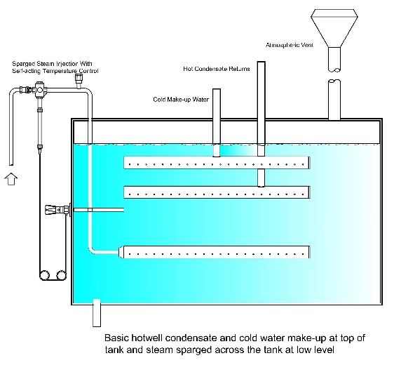
‘Atmospheric Deaerator System’ refers to the combination of a feedtank with central mixing head and immersion/distribution tube on to which the cold water make-up, condensate returns and flash steam from heat recovery systems are connected. Providing that the condensate returns and cold water make-up are adequately controlled so that they both run continuously all is well providing that is, that the immersion tube is the correct length to achieve the correct mixing inside the tank.
However, the biggest drawback is when the cold make-up water flow is operated on/off. When the water level falls and the pressurised cold water control kicks in, then all the cold water is guided down the central immersion tube and deposited at the bottom of the tank where it is sucked into the boiler feed outlet at the dictates of the feed pump. Feedwater temperature drops and the boiler and steam system are put at risk as the oxygenated water flows to the boiler. Personally, I have witnessed the feedwater temperature at the tank outlet drop by 10°C when the cold water kicks in and the feedwater didn’t reach its normal temperature for about 10 minutes after the make-up water switched off. So, the perceived benefits of condensing flash steam or mixing with hot condensate returns don’t really exist.
The logical answer is to spray the cold water into the top of the tank where it will condense any flash steam that is hanging around waiting to discharge up the vent before slowly gravitating through the hot stored water. Granddad wasn’t that far wrong with the basic feedtank design, was he?
Tank Mixing & Heating
For efficient feedtank operation it is important to prevent temperature stratification by adequately mixing all the water streams and maintain the stored water at a constant temperature. The higher the better. Temperature stratification within the tank means that the temperature of the water supplied to the boiler is prone to fluctuation and with it the oxygen content. You can’t adjust in real time the chemical dosing rate of a fixed rate dosing pump to match the varying amount of oxygen scavenging chemical that is required. The boiler output is also affected. The “from and at” rating is at 100OC, if the feedwater is substantially cooler, then the boiler output will be significantly reduced. The higher the feedtank temperature the less chemicals necessary to drive off the entrained oxygen in the makeup water with the additional benefit of a reduction in boiler blowdown.
A centrally installed mixing head appears, on the face of it at least, to be a good idea but is it? No.
It is doubtful whether or not mixing can be adequately achieved with a rectangular shaped tank and a centrally mounted mixing head especially when the boiler feed outlet is in one corner of the tank. Whilst the inclusion of a direct steam injection heating system will encourage mixing, the water stream will be predominately from the central immersion tube outlet towards the feedwater outlet as the feed pumps draw the water out to supply the boiler plant.
Whilst direct steam injection control systems, when correctly sized and adequately installed work well, there are many installations that give rise to problems. When the control valve is on the small size and remains open for long periods, or the steam supply is incorrectly sized leading to high velocity steam flows, then problems with noise and vibration do occur. When the steam supply is fitted to the side of the tank the vibration is transferred to the tank wall and if constructed from stainless steel can work harden and stress cracking results. You will know if it has happened to you as the boilerhouse floor will be wet.
Obviously, not all rectangular feedtanks give trouble. Many carry out their task more than adequately. As engineers we also know from experience that there is no “one shoe that fits all”, but all that we want from the humble feedtank is one body of water at a uniform temperature with a minimum oxygen content available twentyfour-seven.
The challenge is to come up with a design that builds on the strengths of the existing whilst eliminating the weaknesses. Malvern, MD at Coulton Instrumentation, has always insisted that the key to good control is to reduce the variables to a minimum before applying the control logic. He’s never understood the logic of adding cold water to a tank of hot water and then having to inject steam to raise its temperature back to where it was prior to adding the cold water.
Logic says that you should raise the temperature of the cold water before you add it to the tank thereby ensuring a constant water temperature and, if you are serious about “saving the pennies” the higher the temperature the better.
High temperature = Less oxygen = Less chemicals = Less Blowdown = Reduction in waste and saving energy.
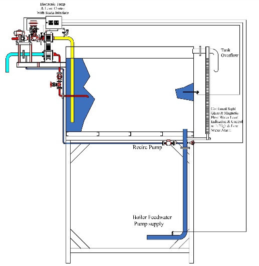
At Controls 4 Steam we have always believed that the present tank design could and should be improved. Over the years we have incorporated some of our design ideas to improve water management in an attempt to iron out short comings such as side entry steam injection; centrally mounted mixing head; length of the immersion tube and the number of tank connections below the water line. Finally settling on a tank design with an external heat exchanger and sparging the heated make-up water into the furthest corner from the feed water outlet. In so doing, eliminating the noise and vibration associated with direct steam injection and ensuring the maximum time for mixing of the contents. But our solution still required the feedtank to be elevated. Then the penny dropped.
Perhaps it is time to redesign the humble feedtank and eliminate the shortcomings of the present rectangular tank. Ask any Process Engineer involved with the mixing and temperature control of stored liquid, what the best tank shape is? The answer won’t be cuboidal but a circular vertical tank.
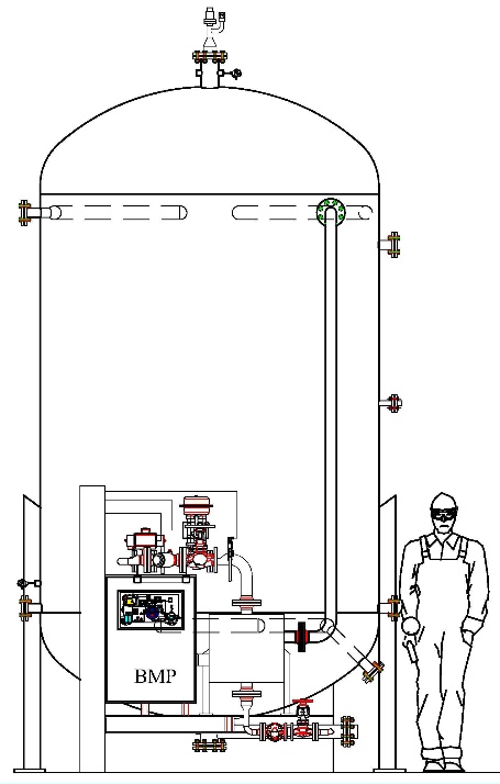
A circular tank with all water streams discharging into the top of the tank, external make-up water heating, eliminating noise and vibration associated with direct steam injection and central discharge at the base ensures mixing and a constant fluid temperature. The circular tank will have dished ends allowing the tank to be pressurised eliminating low NPSH and pump cavitation. Solving the problems associated with pump cavitation enables the stored water temperature to be increased to 100°C and beyond. As you no longer rely on a constant static head the tank can be floor mounted eliminating the need for an elevated platform with ladder access and walkway. With an enclosed tank oxygen content is fixed so you can accurately pre-treat without the risk of re-entrainment. Last, but not least, the controls and heat exchanger can be installed at low level giving easy, safe access by maintenance staff.
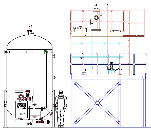
A like-for-like comparison between the existing rectangular tank and support frame and the floor mounted circular vertical tank clearly illustrates that the circular tank design is a cost effective, viable option. Don’t forget that the 2m x 2.5m x 2m tank only holds about 7.5m3 of water compared to the circular tank which holds 10m3. But changing the shape of the tank is only part of the answer.
The devil is in the detail and when it comes to the control of the tank contents Controls 4 Steam lead the way with an integrated control solution that includes pressure, level, temperature, oxygen treatment control and condensate monitoring.
{jd_file file==8}